COMPANY NEWS
Air Shower Pass Boxes: Structure, Principles, and GMP-Compliant Applications
In industries with stringent environmental cleanliness requirements—such as pharmaceuticals, biosafety, microelectronics, food production, and fine chemicals—the transfer of materials between zones of varying cleanliness levels is a critical link in the chain of contamination control. Dust particles, fibers, and microbial spores adhering to the surfaces of packaging, equipment, or raw materials can compromise the cleanliness of a controlled environment if introduced into a cleanroom, potentially leading to cross-contamination and risks to product quality.
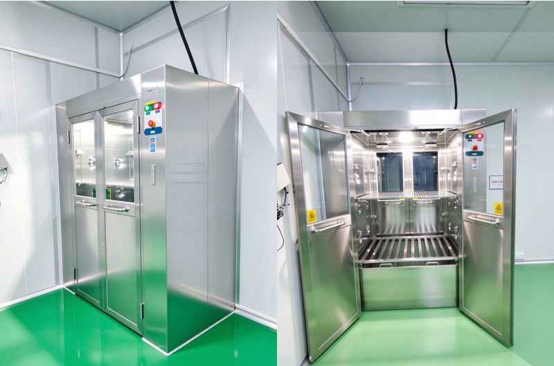
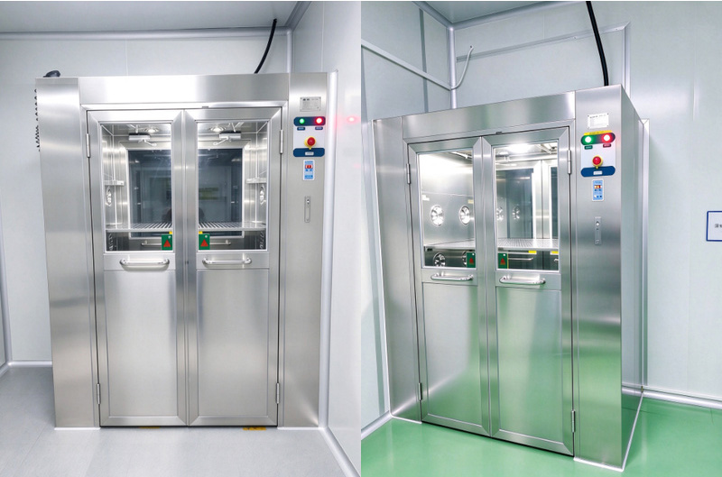
An air-shower pass box (also known as an air-shower pass-through or a pass-through cabinet with an integrated air-shower function) is installed within the wall separating a clean zone from a non-clean zone, or between zones of different cleanliness levels. It allows for the transfer of materials without requiring them to pass through personnel access points. By utilizing high-velocity, filtered airflow to remove surface dust, combined with an interlocking mechanism and an airtight design, it prevents the mixing of air between the two zones, serving as a "safety gateway" for the inter-zonal transfer of materials.
I. Definition and Functional Role of the Air-Shower Pass Box
Material Transfer and Airtight Isolation
The air-shower pass box is an advanced version of a standard pass-through unit. Unlike conventional mechanical or electronic interlocking pass-throughs—which serve only to facilitate material transfer while maintaining airtight isolation—the air-shower pass box is equipped with a High-Efficiency Particulate Air (HEPA) filter, a centrifugal fan, and a set of nozzles. Once materials are placed inside, high-velocity, clean airflow is directed from the sides or the top to shower the outer surfaces of the packaging, dislodging and removing adhering dust and particles. The contaminated air is then processed through a primary filter, pressurized by the fan, and either recirculated through a HEPA filter or, depending on specific process requirements, exhausted directly to the non-clean side.
Core Function
01: Cleaning Function
Utilizes high-velocity, clean airflow to remove dust and particles adhering to the outer surfaces of materials, containers, and equipment, thereby reducing the likelihood of contaminants being carried into the clean zone.
02: Spatial Partitioning Function
The doors on both sides are equipped with a mechanical or electronic interlocking mechanism, ensuring that only one door can be opened at any given time. This prevents a direct connection between the two spaces—thereby avoiding air convection—and stops unfiltered air from backflowing into the cleanroom area.
03: Buffer/Transfer Function
Serving as a buffer node for the transfer of materials between different zones, the unit subjects materials to an air-shower process before they enter the cleanroom side. This reduces environmental disturbances that would otherwise be caused by personnel or materials moving directly through cleanroom corridors.
II. System Structure and Key Components
Air Interlocking System, Air-Shower Circulation System, Filtration Unit, Control and Monitoring Unit
A complete air-shower pass box consists of six main parts: the main housing, the doors and interlocking system, the air-shower circulation system, the filtration unit, the control and monitoring unit, and various accessories.
Q: Main Housing
A: The housing is typically constructed from stainless steel or powder-coated cold-rolled steel. Most standard units are fabricated using 304 or 316L stainless steel sheets that are bent and welded; the interior surfaces are smooth and flat, with no "dead corners" that could hinder cleaning.
Q: Doors and Interlocking System
A: The doors on both sides are generally fitted with tempered glass viewing windows, and the door frames are equipped with sealing strips to ensure an airtight fit when closed. Interlocking systems are categorized into mechanical and electronic types. Mechanical interlocking uses an internal linkage mechanism to prevent both doors from opening simultaneously, while electronic interlocking utilizes electromagnetic locks and control circuitry. The latter can also include status indicator lights and door-opening delay alerts.
Q: Air-Shower Circulation System
A: This system comprises a centrifugal fan, air supply ducts, a set of nozzles, and return-air channels. The fan pressurizes filtered, clean air, which is then discharged through the nozzles as a high-velocity airflow. The nozzles are arranged in an array along the side walls (or a combination of the top and side walls) of the unit, directed at the material surfaces from multiple angles. This creates an enveloping air-shower flow field, minimizing "dead zones" in the airflow. Return air enters the return-air passage from the bottom or the lower side of the unit. It passes through a primary filter before returning to the fan inlet, creating an internal circulation loop.
Q: Control and Monitoring Unit
A: The control system typically includes: fan start/stop controls and air-shower duration settings, door interlock status indicators, an air-shower operation indicator light, high-efficiency particulate air (HEPA) filter differential pressure monitoring (or a port for a differential pressure gauge), and interfaces for power supply and fault alarms. Advanced, intelligent models may feature a touchscreen, operation counters, filter service-life reminders, and communication interfaces for integration with a facility’s Building Management System (BMS) or Environmental Monitoring System (EMS), enabling remote logging of operational data.
III. Working Principle and Operational Workflow
Standard Operating Procedure
When the equipment is in standby mode, both doors are closed and interlocked. To transfer materials, the operator opens the door on the non-clean side, places the materials inside, and closes the door. The interlock mechanism then locks the non-clean-side door, preventing the clean-side door from being opened. The control system activates the fan, forcing clean air through a HEPA filter and out through nozzles at high velocity. This air strikes the surfaces of the materials from multiple angles, dislodging any loose dust. The dust-laden air is then drawn into the return-air passage, passes through a primary filter, and re-enters the circulation loop. (Some models allow for the exhaust of dust-laden air—after it has passed through a HEPA filter—directly to the outside.)
Once the air-shower duration has elapsed, the fan stops, and the clean-side door unlocks. The operator removes the materials from the clean side and closes the door, returning the equipment to standby mode. Throughout this process, the doors on both sides can never be opened simultaneously, effectively preventing direct airflow between the two spaces.
Standard Operating Procedure
1. Verify that the interlock system, fan, and filters are functioning correctly, and ensure the interior is clean and free of debris.
2. Open the door on the entry (non-clean) side, place the materials to be transferred in the center of the unit—ensuring they do not obstruct the nozzles or the return-air passage—and close the door.
3. Initiate the air-shower cycle. Set the duration according to the cleanliness requirements for the materials (typically ranging from several tens of seconds to a few minutes) to complete the surface-cleaning process. 4. Once the air-shower cycle is complete, open the door on the discharge side to remove the materials, then close the door.
5. If the outer packaging of the materials is visibly contaminated, it must be cleaned and disinfected (e.g., by wiping) on the non-clean side before being placed into the chamber. If necessary, the interior of the chamber should also be wiped down and disinfected using ultraviolet (UV) light.
Contamination Control Logic: Interlocking and Sealing
Contamination control in an air-shower pass box relies on two fundamental principles: first, airflow purification—the air used for the shower is passed through high-efficiency filters to prevent secondary contamination of the material surfaces; second, physical isolation—an interlocking mechanism ensures that the doors on both sides cannot be opened simultaneously, while the airtight design of the chamber minimizes air leakage. Together, these features ensure that materials are surface-cleaned during transfer between zones without creating a direct airflow path between clean and non-clean areas.
IV. Key Performance Indicators and Compliance Requirements
Air-shower velocity, filtration efficiency, and interlocking/airtightness.
Q: Air-shower velocity and nozzle parameters
A: The air velocity at the nozzle outlets typically needs to be quite high (commonly exceeding 20 m/s in the industry; specific requirements depend on equipment design and process specifications) to ensure sufficient force to dislodge contaminants. The number of nozzles, their orientation, and their coverage area should be designed based on the internal dimensions of the chamber and the shape of the materials, ensuring that all surfaces are reached by the airflow and minimizing "dead zones" where air does not circulate. Air velocity can be measured at individual points during factory testing and verified again during on-site acceptance.
Q: Filtration efficiency and filter integrity
A: High-efficiency filters must have a specified filtration grade (e.g., H13/H14), and their efficiency in capturing particles of a given size must meet relevant standards. The equipment should come with a factory leak-test report for the filters. Following on-site installation, filter integrity testing (such as a PAO/DOP aerosol leak test) must be performed in accordance with established standards to confirm that there are no leaks in the filter media or the mounting frame. Primary (pre-) filters should be designed for easy removal and replacement.
Q: Interlock Reliability and Airtightness
A: The interlock mechanism must operate reliably, ensuring that both doors cannot be opened simultaneously under any circumstances. Once the doors are closed, the sealing gaskets must be compressed uniformly. The airtightness of the unit should be verified through pressure decay or air leakage rate testing to prevent cross-contamination between the environments on either side due to leaks.
Q: Cleanliness and Material Compliance
A: The unit and all components that come into contact with materials must be constructed from corrosion-resistant, non-shedding, and easy-to-clean materials. Surface roughness must meet cleanroom standards, with no "dead zones" where dust can accumulate. For equipment used in pharmaceutical production areas, materials, surface treatments, and cleaning/disinfection methods must comply with relevant GMP requirements. For components that come into contact with the product or are located within Grade A/B environments, material compatibility and cleanability must be assessed.
Validation and Documentation Requirements
In pharmaceutical and highly regulated environments, air-shower pass-through boxes—as auxiliary cleanroom equipment—must be integrated into the facility’s equipment validation system. This typically includes:
Design Qualification (DQ): Verifying that the equipment structure, materials, configuration, and specifications align with process requirements.
Installation Qualification (IQ): Verifying the installation location, mounting method, utility (piping/electrical) connections, and the availability of accompanying documentation.
Operational Qualification (OQ): Testing the interlock mechanism, fan operation, air-shower duration control, indicator lights, and alarm functions.
Performance Qualification (PQ): Testing air-shower velocity, internal cleanliness, filter integrity, and airtightness under simulated operational conditions.
The equipment must be accompanied by a complete set of technical documentation, including a factory certificate of conformity, material certificates, filter test reports, and operation and maintenance manuals.
V. Daily Operation and Maintenance Protocols
Operational Essentials and Routine Maintenance
Installation Requirements
1. The equipment must be installed within a pre-cut opening in the wall. The gap between the unit and the wall must be filled with sealing material to ensure a tight partition between the two sides. For flush-mounted installations, the doors must be level with the wall surface, with smooth, sealed edges all around.
2. The equipment must be reliably grounded, and electrical connections must comply with the facility’s electrical standards. For models equipped with an exhaust function, the exhaust ductwork must be connected in accordance with cleanroom and safety requirements. 3. The installation location should facilitate the loading and unloading of materials by operators on both sides, while avoiding placement directly in the path of primary personnel traffic or in areas critical to the facility’s airflow distribution.
Operational Management Guidelines
1. Before placing materials into the unit, remove any visible dust or stains from their outer packaging; packaging that is soiled must not be introduced directly into the air-shower pass-through box.
2. Do not force the doors open during the air-shower cycle. Do not attempt to pry open the doors or tamper with the locking mechanisms while the interlock system is engaged.
3. Materials should not be stored inside the unit for extended periods, as this can lead to the accumulation of dust and the growth of microorganisms.
4. Maintain records of equipment usage and cleaning, including details on air-shower operation, cleaning and disinfection, filter replacements, and any operational anomalies.
Routine Maintenance and Care
1. Cleaning and Disinfection: Regularly wipe down the interior walls, nozzles, and air-return slots to remove accumulated dust. Ensure that the chosen disinfection methods and agents are compatible with the materials used in the unit’s construction.
2. Filter Maintenance: Periodically inspect the primary (pre-) filters for clogging and clean or replace them as necessary. Replace high-efficiency (HEPA/ULPA) filters based on pressure differential monitoring and established service intervals; perform an integrity leak test following any filter replacement.
3. Interlock and Seal Inspection: Regularly verify the proper functioning of the door mechanisms, door seals (gaskets), and the interlock system. Replace any seals that show signs of aging or deformation.
4. Fan and Electrical Inspection: Monitor the fan for unusual noise, vibration, or abnormal electrical current. Periodically check electrical wiring, indicator lights, and alarm functions.
5. Periodic Re-qualification: In highly regulated environments, conduct periodic re-testing—covering air velocity, cleanliness levels, filter integrity, and airtightness—in accordance with established validation schedules, and maintain documentation of these results.
Although classified as auxiliary cleanroom equipment, the air-shower pass-through box serves as a critical link in the transfer of materials between different zones. Through its integrated design—combining surface air-showering, interlocked isolation, and high-efficiency filtration—it provides a controlled, clean transition channel for materials entering or exiting a cleanroom, all without compromising the facility’s overall airflow dynamics. Against a backdrop of increasingly stringent GMP compliance and ever-rising requirements for clean environments, it is only through proper selection, standardized usage, and rigorous validation and maintenance that this "safety barrier" can truly fulfill its function—providing a reliable safeguard for both product quality and the production environment.
