COMPANY NEWS
Comprehensive Analysis of Operational Procedures, Maintenance, and Servicing for Grade A Laminar Flow Hoods
A Grade A laminar flow hood is an air purification unit designed to provide a localized, high-cleanliness environment. It primarily consists of a housing, a fan, a pre-filter, a HEPA/ULPA filter, lighting, a flow-equalizing membrane, and a control system. The unit can be either suspended or floor-mounted; it features a compact design and is easy to operate. The housing is constructed from anti-fingerprint 304 stainless steel, offering an aesthetically pleasing, clean appearance that is simple to sanitize. These units are primarily used in the electronics, pharmaceutical, and bioengineering industries.
I. Structural Schematic
Vertical Flow / Horizontal Flow
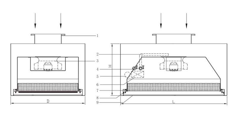
Q: Laminar Flow Design
A: Airflow follows a horizontal or vertical flow pattern.
Q: Fan
A: Equipped with EBM-310/EBM-355/XM-310/XM-355 centrifugal fans, featuring low noise and minimal vibration.
Q: Filter
A: Includes a black nylon mesh pre-filter (designed to capture airborne dust particles larger than 1μm, thereby reducing the load on the high-efficiency filter and extending its service life). The high-efficiency filter is an H14-grade unit (99.997% efficiency for 0.3μm particles) featuring a liquid-seal design.
Q: Differential Pressure Function
A: Displays the filter differential pressure with an accuracy of ±5 Pa; used to monitor the airflow resistance of high-efficiency filters, thereby helping to assess their operational status.
Q: Control Function
A: Controlled via a variable-frequency drive (VFD), with buttons for starting, stopping, and setting the fan.
Operating Principle: The laminar flow hood utilizes a vertical or horizontal airflow pattern. Return air first passes through a primary filter to remove large dust particles. Driven by the pressure generated by a centrifugal fan, the pre-filtered air then passes through a liquid-seal HEPA (high-efficiency particulate air) filter to meet cleanliness requirements. Finally, the clean airflow travels through a 200-mesh diffusion screen, ensuring a uniform velocity as it reaches the work area.
II. Product Installation
Requires a clean environment with a high level of cleanliness.
The laminar flow hood is designed for installation in high-cleanliness environments. Surrounding walls and surfaces should be treated to ensure they do not generate dust. The unit requires a 220V/50Hz power supply and should be operated in an environment with a temperature range of 10°C–35°C and a relative humidity (RH) range of 40%–70%.
Precautions:
Disconnect the power supply during installation to prevent electric shock.
Ensure the unit housing does not come into contact with other objects during installation to avoid scratching the surface.
Verify that all components are securely fastened and that there are no loose parts.
Adhere strictly to the specified environmental requirements; failure to do so may impair the performance of the laminar flow hood, lead to short circuits, damage electrical components, and shorten the unit's service life.
Install the unit away from heaters, stoves, or other heat sources.
Do not place flammable materials in the installation area, as this poses a fire risk.
The use of explosive or volatile chemicals is strictly prohibited; the unit may draw in these substances, potentially causing a fire or explosion.
Do not install the unit in environments containing sulfuric acid, hydrochloric acid, or other corrosive chemicals, as this may lead to corrosion and damage to the equipment.
After installation, wipe the interior and exterior of the unit housing clean.
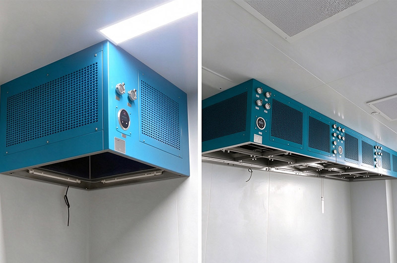
III. Pre-Operation Checks
Component Integrity and Efficiency Verification
1. Confirm that all components of the laminar flow hood are correctly installed.
2. Verify that the external power connection is secure and the power supply is functioning properly.
3. Ensure that the air intake at the top is not obstructed; blockages can prevent the unit from operating as intended, potentially causing functional malfunctions or damage to electrical components.
4. Press the "RUN" button on the control panel, turn on the unit’s power switch (following the "Inverter Switch Operation Instructions"), and adjust the power setting as required. The unit's fan should operate normally, without any abnormal noise or excessive vibration. 5. Laminar Flow Hood Filtration Efficiency Testing: Perform an integrity test on the fluid-seal HEPA/ULPA filters using a PAO aerosol photometer and an aerosol generator. The test should be conducted at a distance of 25.4 mm from the air outlet surface, with a scanning speed not exceeding 5 mm/s. The leakage rate must be less than 0.01%.
6. Laminar Flow Hood Air Velocity Testing: Measure the air velocity 100–150 mm below the air-distribution screen (diffuser screen) using an anemometer. The average air velocity should be 0.45 m/s ± 20%.
7. Turn off the fan switch and disconnect the power supply when the unit is not in use.
IV. Precautions for Use
Operate according to specifications to avoid hazards.
1. Disconnect the power supply if the equipment malfunctions or requires maintenance.
2. Do not use chemical solvents (such as paint thinners/lacquer thinners) to clean the stainless steel surfaces.
3. Do not use compressed air to blow directly onto the HEPA/ULPA filters at close range.
4. For units equipped with germicidal (UV) lamps: Be aware that the ultraviolet (UV) light can penetrate and kill cells. Ensure that the UV light does not shine directly onto human skin or eyes. Do not look directly at the UV lamp while it is illuminated. Since short-wave UV light cannot pass through ordinary glass, wearing eyeglasses can help protect the eyes. In the event of accidental eye exposure, the effect is generally similar to a sunburn; in more severe cases, eye drops or human breast milk may be used to aid recovery.
5. Before replacing fluorescent or germicidal lamps, disconnect the power supply and allow the lamps to cool down to prevent burns from high temperatures.
6. Do not place objects near the air return vents, as this may restrict airflow intake and reduce the unit's self-purification capacity.
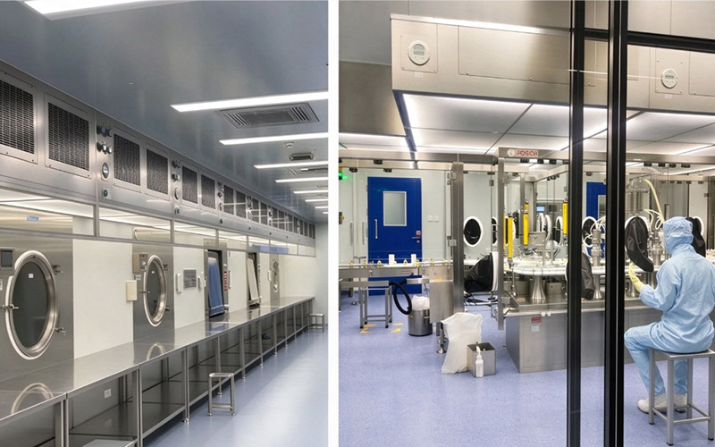
V. Maintenance and Care
Periodic Inspection and Maintenance Procedures
This equipment must be maintained and serviced by professionally trained personnel. If any abnormalities are detected, disconnect the power supply immediately and take corrective action. Routine maintenance and inspection:
Q: Periodic Inspection: Motor
A: Criteria for Assessment:
Check the motor for any unusual noise, vibration, or odors; listen for abnormal sounds from the bearings; and inspect cables and terminals for damage or corrosion.
Signs and Potential Causes:
Damaged bearings may cause the motor to run unevenly or seize (lock up).
Poor power connections or faulty terminal insulation can lead to abnormal heating, grounding errors, or short circuits.
Q: Periodic Inspection: Fan
A: Acceptance Criteria:
Check the centrifugal fan for abnormal noise, vibration, or damage; replace any faulty components.
Signs and Potential Causes:
Bearing damage resulting from an imbalance in operation, caused by the accumulation of dust or physical damage to the bearing itself.
Q: Periodic Inspection: Primary (Pre-) Filter
A: Acceptance Criteria:
Visually inspect the filter media, gaskets, and sealing components for scratches, discoloration, or deformation.
Signs and Potential Causes:
Reduced airflow velocity due to clogging.
Deterioration of filter media, gaskets, or sealing components—potentially caused by exposure to chemicals—leading to dust leakage.
Deterioration of filter media caused by external heat sources.
Q: Periodic Inspection: Outer Casing and Other Components
A: Acceptance Criteria:
Visually inspect components for defects, such as discoloration or scratches.
Signs and Potential Causes:
Corrosion or rust on components—caused by exposure to chemical agents—resulting in the generation of dust/particulate matter.
Q: Periodic Inspection: Other Electrical Components and Wiring Materials
A: Acceptance Criteria:
Check for signs of corrosion, exposed conductors, or damage to wire insulation.
To verify that filtration efficiency meets cleanliness requirements, perform an integrity test on the HEPA/ULPA filters and their mounting frames using a PAO aerosol photometer and an aerosol generator. The test should be conducted at a distance of 25.4 mm from the air discharge surface, with a scanning speed not exceeding 5 cm/s; the leakage rate must be less than 0.01%.
Air velocity measurement method: Use an anemometer to measure air velocity at a distance of 150–300 mm below the air-distribution screen (diffuser screen). The average air velocity should be 0.45 m/s ± 20%.
Signs and Potential Causes:
Poor insulation or loose terminal screws, which may lead to overheating, short circuits, or burning.
Reduced air velocity due to obstructions (clogging).
Troubleshooting
01: Electrical Malfunctions
In the event of a device malfunction, you may attempt repairs yourself by following the instructions in the manual, or contact our customer service department to request an on-site repair. For products within the warranty period, we provide repairs free of charge (excluding damage caused by user misuse or mishandling). For products beyond the warranty period, a fee will be charged based on the cost of any replacement parts used. (Note: Unauthorized modifications to the electrical circuitry or structure are not covered under warranty. Consumables—such as filters, lighting fixtures, and air-distribution membranes—are also excluded from the warranty.)
02: Abnormal Cleanliness Test Results
If cleanliness test results fail to meet technical specifications, inspect the filter media for damage and ensure the filter clamping blocks are securely tightened. If these checks are satisfactory but leaks persist, wipe the filter frame with alcohol and re-verify. If the filtration efficiency still fails to meet requirements, the HEPA (high-efficiency) filter must be replaced.
03: Abnormal Airflow Velocity Test Results
If the average airflow velocity of the Fan Filter Unit (FFU) is measured below 0.35 m/s, first verify that the fan is operating correctly. If the fan is malfunctioning, you may attempt repairs according to the instruction manual or contact our customer service department to request an on-site repair. If the fan is operating normally, replace the primary (pre-) filter or the HEPA filter.
Procedure for Replacing Primary (Pre-) Filters: Remove the old primary filter from its frame and install the new one. (If the primary filter is housed within a mesh panel, the panel must be removed first to facilitate the replacement.)
Procedure for Replacing HEPA Filters:
a. Before installing a HEPA filter, thoroughly clean and wipe down the cleanroom and the fan housing unit. Any accumulated dust within the purification system must also be removed.
b. Disconnect the power supply and prepare the replacement HEPA filter.
c. Ensure the new HEPA filter matches the specifications and model of the original unit.
d. Upon unpacking the new filter, perform a visual inspection: check for damage to the filter media, ensure the frame is free of deformation or gaps at the joints, and verify that the clamping blocks are secure.
e. After installation, confirm that there are no leaks around the filter frame. Conduct a PAO (polyalphaolefin) integrity test to ensure compliance with technical specifications. The unit is ready for normal operation only when the average airflow velocity is maintained at 0.45 m/s ± 20%.
