COMPANY NEWS
Detailed Overview of Customized Solutions for Aseptic Filling Lines, Freeze Dryers, and Multi-Station Grade A Laminar Flow Hoods
High-risk operations—such as aseptic pharmaceutical filling, freeze-dryer loading and unloading, capping, stopper buffering, aseptic transfer, and weighing/dispensing—must rely on stable and controllable Grade A (ISO 5 / Class 100) vertical unidirectional airflow to isolate against particulate and microbial contamination.
For over a decade, AN has specialized in the high-end clean sterilization sector. Leveraging in-house capabilities in sheet metal fabrication, proprietary filter development, and automated control system engineering, the company offers a customized, non-standard Grade A laminar flow hood system. Designed for the diverse workstations found throughout pharmaceutical manufacturing, this modular, integrated solution supports seamless equipment interconnection and comprehensive process validation. It covers a full range of applications—including main filling lines, freeze-dryer interfacing, capping stations, equipment unloading, aseptic transfer, and negative-pressure weighing—effectively resolving industry pain points such as turbulent airflow, air leakage and pressure loss, contamination during equipment docking, poor sterilization compatibility, and a lack of data traceability. The system is adaptable to various requirements, including new facility construction, the retrofitting of existing production lines, and upgrades to integrated freeze-drying and filling lines.
I. Basis for Scheme Design and Mandatory Standards
Class A General Mandatory Technical Specifications
| Test Item | International Standard Requirements |
| Cleanliness | Grade A Static / Dynamic ISO 5 |
| Cross-sectional Air Velocity | 0.36–0.54 m/s |
| Microbial Control | Floating Bacteria ≤5 CFU/m³; Settling Bacteria ≤1 CFU/4h; Φ90 mm Petri Dish |
| Filter Grade | Mandatory H14 HEPA Filter |
| Leakage Control | No Visible Leakage After Filter Installation |
| Self-cleaning Time | ≤20 min |
AN Core Universal Structure Configuration
Grade A laminar flow hood
01: Main Structure
Enclosure: SUS316L mirror-finish stainless steel (for high-humidity environments and frequent VHP sterilization) or SUS304 stainless steel; constructed via integrated bending and full-seam welding, featuring internal corner radii of R≥5mm and an internal surface roughness of Ra≤0.6μm; designed with no seams or dead zones and free of silicone sealant to eliminate dust and bacterial accumulation. Frame: Heavy-duty aluminum alloy load-bearing structure, available in four mounting configurations: ceiling-suspended, floor-stand, mobile (caster-mounted), and rigid-docking.
02:Filtered air supply system
Features a primary filter, static pressure equalization plenum, dual-layer air deflectors, polyester flow-equalizing membrane, and an H14 gel-seal HEPA filter; V-shaped, densely pleated media triples the filtration area and eliminates corner turbulence; comes standard with an independent PAO aerosol leak test port and pressure differential monitoring ports (upstream and downstream).
03:Powertrain system
Features a quiet EC variable-frequency fan with 4–20mA/Modbus-RTU communication; automatically compensates airflow for filter clogging; ensures consistent temperature control and noise reduction during long-term operation; and is suitable for 24-hour continuous production in workshop environments.
II. Customization of Class A Laminar Flow Hoods for the Full Filling Line
Highest-risk core workstation
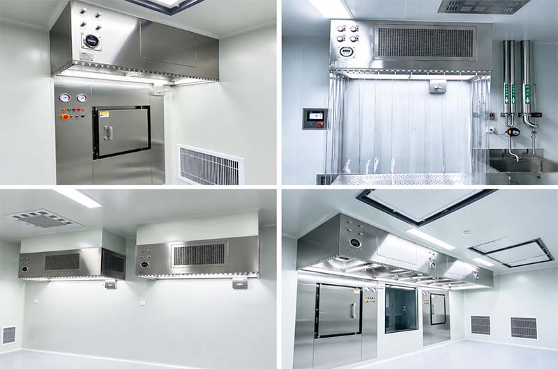
Applicable workstations include pre-filled syringe filling, vial filling, liquid injection filling, powder injection filling, filling heads, rubber stopper feeding zones, open-vial transport tracks, and the transfer path between filling and capping; these are primarily located in Grade A environments with Grade B backgrounds.
Industry pain points: Airflow turbulence at the vial opening entraining ambient dust; vortexes generated by manual handling; contamination from dropped stoppers; dust accumulation in the gap between the laminar flow unit and the filling machine; and inconsistent air pressure across segmented laminar flow sections.
Q: Integrated modular linear laminar flow unit
A: An integrated laminar flow enclosure is constructed using seamlessly joined multiple FFU modules, providing full coverage over the filling heads, bottle conveyor lines, and stopper hopper placement areas; equipment must not be positioned so that it is partially inside and partially outside the laminar flow zone. A 150 mm clearance for cleaning and maintenance is maintained between the equipment sidewalls and the laminar flow enclosure panels to facilitate the routing of CIP/SIP piping and routine wiping and disinfection.
Q:Airflow optimization design
A:The entire ceiling is fully covered with H14 filters and a dual-layer laminar flow screen, delivering vertical unidirectional airflow directly onto the vial openings; CFD simulations were used to model extreme scenarios—such as manual intervention, stopper replacement, and vial jams—to eliminate turbulence caused by hand movements. Flexible, transparent, anti-static barriers are installed on both sides of the filling area, featuring a 120mm air curtain outlet in the lower section; the downward airflow generates a lateral air curtain that blocks the intrusion of turbulent air from the Grade B zone.
Q: RABS Containment Upgrade Solution
A: An open-style laminar flow system upgraded to a Restricted Access Barrier System (RABS): it features raised stainless steel enclosures on all four sides, with access limited to sterile silicone rubber glove ports and RTP (Rapid Transfer Port) interfaces. The internal chamber utilizes expanded laminar flow and maintains a +5 Pa positive pressure, minimizing direct human intervention throughout the process and significantly reducing dynamic microbial risks—specifications that can be directly incorporated into the Contamination Control Strategy (CCS) documentation.
Q: Coordinated supporting facilities
A: The laminar flow control system is interlocked with the filling machine's PLC for synchronized start-stop operation; during filling pauses, the system maintains stable, low-speed airflow to ensure the Grade A environment remains undisturbed. Low-level return air ducts located beneath the track promptly collect fallen stoppers and powder, preventing dust from becoming airborne again.
III. Customization of Grade A Laminar Flow Hoods for Freeze-Dryer Loading and Unloading Interfaces
Challenges in cross-equipment integration for critical workstations
Applicable workstations: freeze-dryer chamber door interfacing, transfer channels for the entry and exit of vials (with stoppers partially inserted), temporary storage and unloading zones, and buffer/isolation zones before and after freeze-drying; these represent critical connection points between the filling and freeze-drying processes.
Industry pain points: airflow backflow upon opening/closing the freeze-dryer door; exposure of vials during transfer; imperfect sealing between the laminar flow system and the freeze-drying chamber; fan condensation under low-temperature operating conditions; and inability to perform synchronized, comprehensive VHP sterilization.
AN Rigid Docking Customization Solution:
Q: Rigid airtight docking structure
A: A laminar flow enclosure featuring an integrated flange connection is custom-engineered to match the specific model of the freeze-dryer. It connects to the freeze-dryer door via a silicone rubber airtight seal, ensuring a seamless fit with no gaps or dead zones. The enclosure body allows for fine-tuned extension and retraction to accommodate the door's opening travel; upon opening, the laminar airflow undergoes instantaneous pressurization to create a sealed air barrier, preventing external contaminated air from entering the chamber.
Q: Specialized design for low-temperature condensation prevention
A:The fan and static pressure chamber are insulated, and the inner walls are equipped with constant-temperature trace heating to prevent moisture condensation and dripping—caused by the low-temperature freeze-drying environment—from contaminating the vials. The filters utilize specialized low-temperature and VHP-resistant fiberglass media, ensuring stable performance without degradation across an operating range of -10°C to 60°C.
Q: Dual-channel layered design
A:Upper level: A clean transfer channel providing Grade A unidirectional airflow protection for semi-stoppered vials throughout the process. Lower level: A return-air disinfection channel integrated with a compact VHP atomization port; this enables synchronized in-situ sterilization linked with the freeze-dryer chamber, establishing a sterile, closed-loop system for the entire freeze-drying and filling line.
Q: Automated Adaptation
A: It can be paired with an automatic loading and unloading robotic arm; a passage window for the arm is reserved within the laminar flow zone, and the window automatically generates a localized air curtain as the arm moves, ensuring the overall unidirectional airflow remains undisturbed; an independent differential pressure interlock system automatically increases the internal chamber air pressure if the freeze-drying door is not fully closed.
IV. Summary of Customized Solutions for Common Workstation Configurations
Air Shower, BIBO, Pass Box, Laminar Flow Hood
1.Laminar flow hood for sterile equipment unloading
Features a dedicated laminar airflow system at the discharge outlet and an independent, sealed chamber to prevent secondary contamination during the transfer of sterilized instruments; equipped with a VHP port and a double-door interlock system, it serves as a buffer zone between the sterilizer and the clean area.
2.Laminar flow hood for temporary storage of rubber stoppers/aluminum caps
A compact, standalone laminar flow unit features an adjusted, moderate airflow velocity of 0.38–0.42 m/s—ensuring a gentle stream that does not dislodge rubber stoppers—and utilizes raised side enclosures to keep materials within the supply airflow zone throughout the process.
3.Laminar flow hood for negative-pressure weighing booth
The weighing booth features reinforced laminar airflow from the top combined with negative-pressure exhaust at the bottom, achieving localized Grade A cleanliness and directional dust collection; it is suitable for weighing APIs and highly potent drugs, preventing cross-contamination and protecting personnel from inhaling drug dust.
4.Long-strip laminar flow hood for transfer passageway
Enables long-distance transfer between filling, freeze-drying, and capping stations; features modular, flexible configuration that allows for future extension as needed; and utilizes a lightweight overhead design that does not occupy valuable floor space in the production area.
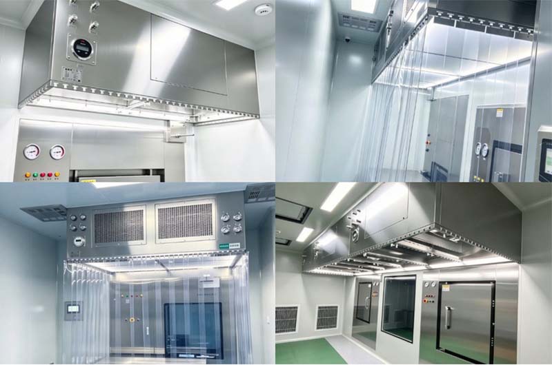
AN provides a complete validation documentation package for each custom laminar flow hood unit:
Design phase: URS (User Requirements Specification).
Factory-stage reports: PAO filter leak test, smoke airflow visualization test, air velocity uniformity test, and airtightness test.
On-site phase: Complete templates and on-site commissioning for IQ (Installation Qualification), OQ (Operational Qualification), and PQ (Performance Qualification).
After-sales services: On-site leak detection and calibration, filter replacement and maintenance, cleanroom remediation and optimization, and long-term technical support.
Summary of Key Advantages of AN Products:
In-house core components: Independent production of H14 filters and EC fans eliminates outsourcing markups and ensures end-to-end quality control;
Flexible, non-standard customization: No restrictions on dimensions, structure, functionality, or equipment brands; on-site 1:1 measurements enable custom solutions that perfectly fit legacy production line retrofits;
Robust compliance: Strictly aligned with the latest GMP and CCS standards, proactively avoiding laminar flow design flaws often flagged during unannounced inspections;
One-stop service: A full-lifecycle solution covering design, manufacturing, on-site installation, commissioning and validation, and ongoing maintenance.
